


Troubleshoot campervan power systems with confidence
Master your campervan power system with this troubleshooting guide! Learn to diagnose faults easily and avoid costly repairs.
TL;DR:
- Power failures in campervans often follow predictable patterns once system maps are understood, aiding DIY diagnosis. Proper safety checks, correct tools, and knowledge of UK standards are essential for reliable troubleshooting and system safety. When issues persist or involve modifications, consulting a qualified professional ensures compliance, safety, and long-term system performance.
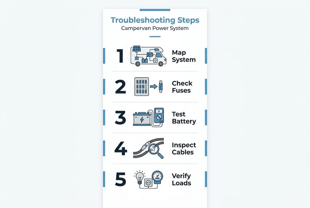
You’re parked up in a remote corner of Snowdonia, the kettle’s just boiled, and suddenly the fridge clicks off and the lights go dark. Sound familiar? Power failures in campervans are more common than most owners expect, and they always seem to happen far from any useful help. The good news is that most faults follow predictable patterns, and a methodical approach will resolve the majority of them without specialist callout fees. This guide walks through the complete process: mapping your system, using the right tools safely, diagnosing DC and AC faults, and knowing exactly when to call in a professional.
Table of Contents
- Understanding your campervan power system layout
- Tools and essentials for safe power troubleshooting
- Step-by-step process: Diagnosing common DC faults
- Diagnosing AC and inverter power issues the UK way
- Final checks, verification, and when to seek professional help
- The biggest pitfalls we see in UK campervan troubleshooting
- Take your campervan power further with expert support
- Frequently asked questions
Key Takeaways
| Point | Details |
|---|---|
| Map before testing | Always start with a clear map of your power system’s components to avoid guesswork and save time. |
| Prioritise safety and standards | Follow UK vehicle wiring standards and disconnect power before working on electrical systems. |
| Check both DC and AC sides | Separate troubleshooting steps for 12V and 230V systems to accurately trace faults. |
| Verify RCD function carefully | Always test RCDs under both shore power and inverter power to ensure safe operation. |
| Know your limits | Get professional help for AC work or if you cannot trace a fault after step-by-step diagnosis. |
Understanding your campervan power system layout
With the problem framed, understanding what you’re working with gives you the strongest foundation for reliable troubleshooting. Before touching a single wire, you need a clear mental map of your entire electrical system. Most campervan owners know they have a battery and some solar panels, but the details in between are where faults hide.
A practical approach, as outlined in component-level mapping, is to identify every component from battery to load and verify voltage and current at each stage rather than guessing from symptoms alone. That means knowing your charge sources, your distribution and protection layer, and every connected load.
| Component | Typical spec | Function |
|---|---|---|
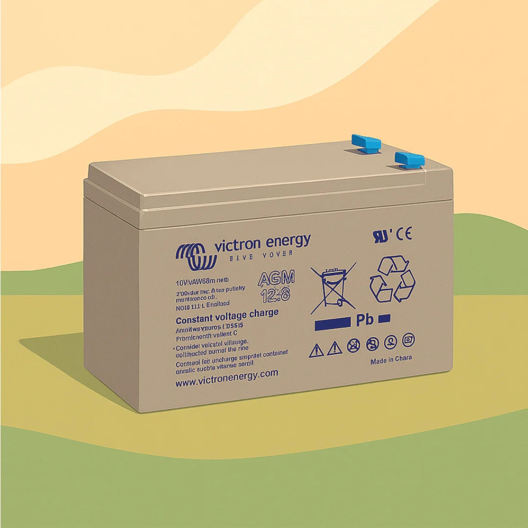
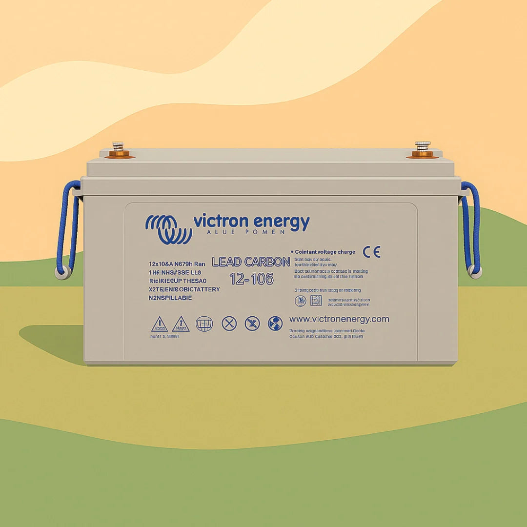
| Leisure battery | 12V, 100Ah–200Ah | Primary energy storage |
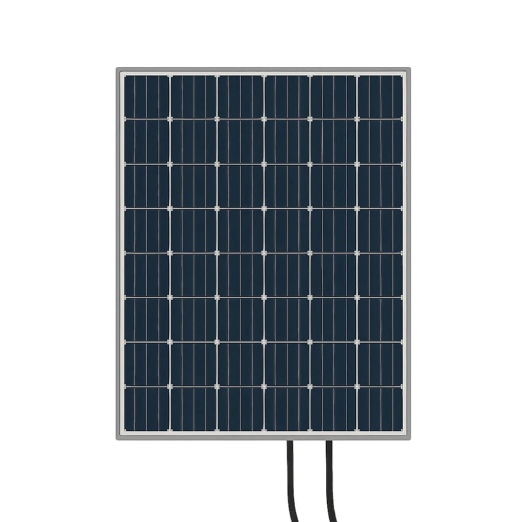
| Solar panels | 12V/24V, 100W–400W | Charge via MPPT controller |
| MPPT charge controller | 12V/24V input, 20A–60A | Regulates solar charging |
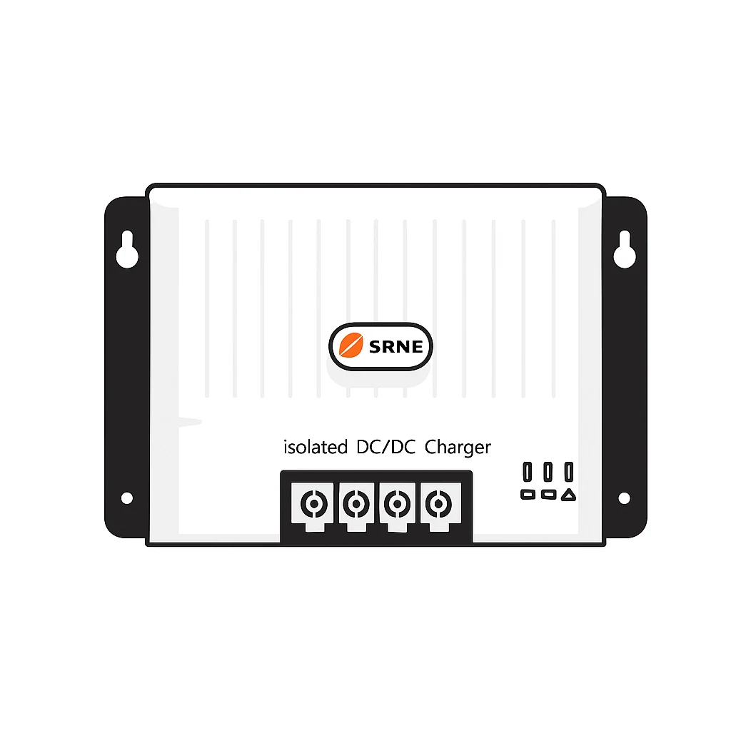
| DC/DC converter (B2B charger) | 12V–12V, 20A–40A | Charges leisure battery from alternator |
| Mains charger (EHU) | 230V AC in, 12V/14.4V out | Charges from campsite hook-up |
| Fuse box or bus bar | 60A–200A rated | Distributes power and protects circuits |
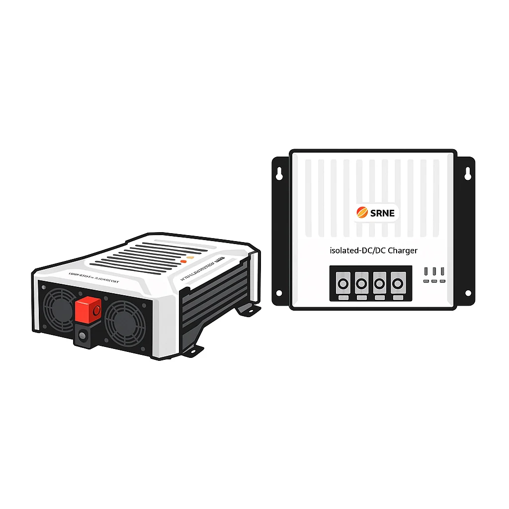
| Inverter/charger | 12V DC in, 230V AC out | Powers AC appliances off-grid |
| Loads (fridge, lights, USB) | Varies by device | Consumers of stored energy |
Understanding these components in relation to each other is critical. When the campervan electrical systems layout is mapped correctly, you can trace a fault from symptom back to source in minutes rather than hours.
Here are the most common power issues and how system knowledge shortens diagnosis:
- No output at any 12V socket: Likely a blown main fuse or a tripped isolator. Start at the battery terminals and work forward.
- Fridge cutting out overnight: Battery state of charge (SOC) dropping below the low-voltage cut-off. Check battery voltage and charge sources.
- Solar not charging: MPPT controller fault, shading issue, or blown inline fuse between panels and controller.
- Lights flickering: Loose connection, undersized cable, or excessive voltage drop on a long run.
- 230V sockets dead but 12V works: Inverter fault, tripped RCD, or issue with neutral-to-earth bonding.
Keeping a basic wiring diagram in the van is one of the most underrated steps in any motorhome energy checklist. Even a hand-drawn sketch beats relying on memory when you’re troubleshooting under stress.
Tools and essentials for safe power troubleshooting
Once you know the system’s main parts, the right preparation ensures your troubleshooting is both safe and effective. Attempting electrical tests without the correct tools is the fastest way to damage equipment or injure yourself.
| Tool | Purpose | Spec/type |
|---|---|---|
| Digital multimeter | Voltage, continuity, resistance tests | Auto-ranging, CAT III rated |
| Clamp meter | Current measurement without disconnecting | DC capable, 0–100A range |
| Insulation resistance tester (megger) | Test for wiring degradation | 500V DC output |
| RCD tester | Verifies trip times on residual current devices | UK 230V rated |
| Crimping tool and terminal kit | Making safe, secure connections | Ratchet-type preferred |
| Wire labels and marker pen | Identifying cables before disconnection | Any type |
| Fuse assortment | On-site replacements | Blade, glass, and ANL types |
| PPE | Safety glasses, insulated gloves | 1000V rated gloves minimum |
For UK compliance, the following points are not optional:
- BS 7671 Section 721 covers fixed wiring in leisure vehicles and sets out requirements for AC installations in campervans.
- BS EN 1648-2 is the specific standard for 12V DC electrical systems in leisure accommodation vehicles.
- RCD testing should be performed on both shore power (EHU, or electric hook-up) and inverter circuits separately. Many owners test only on EHU and miss inverter-mode failures.
- Any system that has been modified must be signed off by a qualified professional before use to maintain compliance and insurance validity.
Check the energy checklist for motorhomes before starting any work on your system to ensure nothing is missed.
Pro Tip: Before any testing, remove all metal jewellery, disconnect non-essential loads, and use only fully insulated tools. A short-circuit at 12V DC can release enormous energy instantly. The risk is low-voltage burns, not electrocution, but damaged wiring and fires are very real outcomes. On the AC side, treat every circuit as live until confirmed otherwise. Review these off-grid power system tips for a full safety overview before you begin.

Step-by-step process: Diagnosing common DC faults
With prep and safety in hand, start by focusing on the DC side, as most off-grid failures originate here. The 12V DC circuit is the backbone of nearly every campervan system, powering the fridge, lights, water pump, USB charging points, and much more.
The step-by-step DC diagnostic process should follow this sequence: list all loads, verify distribution and protection, then test polarity, voltage, voltage drop, and battery health in order.
-
Check all fuses and connections first. Start at the main fuse near the battery positive terminal. Then check each circuit fuse in the fuse box. A visual check is not enough: use your multimeter on the voltage setting to confirm power flows through each fuse (12V on both sides means the fuse is intact). Also inspect every terminal and connector for corrosion or looseness.
-
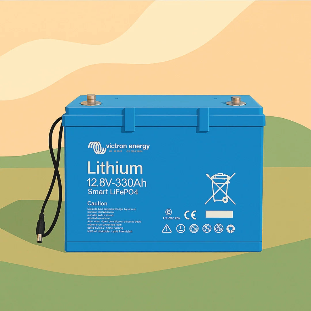
Measure battery resting voltage. Disconnect all loads and charge sources. After 30 minutes, measure across the battery terminals. A healthy 12V AGM battery rests at 12.7V or above. A lithium LiFePO4 battery should show 13.2V or above at full charge. Below 12.0V on an AGM or 12.8V on lithium indicates significant discharge or a possible fault.
-
Test voltage under load at each circuit. Reconnect loads one by one and measure voltage at the consumer’s terminals, not at the battery. For a circuit drawing 10A over a 4-metre run, acceptable voltage drop is no more than 0.5V. More than 0.5V of drop suggests undersized cable or a poor connection somewhere along the run.
-
Check polarity. This sounds basic, but reversed polarity is a common DIY wiring error that destroys equipment silently. Set your multimeter to DC volts and confirm positive is positive at every load terminal. This is especially important when replacing or adding new components. Review the solar battery connection steps for correct polarity procedures.
-
Assess battery health with a load test. Apply a known load (use a dedicated 12V load tester or observe voltage when running a high-draw appliance like a compressor fridge). A healthy battery should not drop below 12.0V under moderate load. If voltage collapses quickly, the battery cells may be degraded. Consider a battery upgrade if the battery is over four years old and showing signs of capacity loss.
Common mistakes at this stage: overlooking the chassis earth connection (the cable from battery negative to the vehicle body), misreading open-circuit voltage as a sign of health, and skipping the fuse test because “it looks fine.”
Pro Tip: Always measure voltage directly at the load’s terminals, not at the battery or fuse box. A fuse box reading of 12.6V can mask a voltage drop to 11.8V at the load due to a bad connection partway along the circuit. That 0.8V drop is enough to cause intermittent faults and false alarms.
Diagnosing AC and inverter power issues the UK way
After DC checks, attention must turn to the more complex and potentially dangerous AC and inverter side. UK campervans operate on 230V AC, either sourced from a campsite EHU or generated by an onboard inverter powered by the leisure battery. These two sources behave differently and require different safety checks.
The critical point: RCD protection must be verified separately under inverter power and shore power, because RCD trip behaviour depends entirely on correct neutral-to-earth bonding for each mode.
-
Test RCD function on mains EHU and inverter mode separately. Press the test button on the RCD with the EHU connected. Then disconnect the EHU, switch to inverter power, and test again. Many owners never test the second mode. An RCD that trips correctly on EHU may fail to trip on inverter power if the bonding is incorrect.
-
Measure neutral-to-earth resistance on the inverter output. Set your multimeter to resistance (ohms) and measure between the neutral and earth terminals at the output of the inverter. Some inverters provide a built-in neutral-to-earth bond; others do not. Without this bond, the RCD has no reference and cannot detect a fault current.
-
Check whether the inverter provides a neutral-to-earth bond. Consult the inverter’s manual or the energy storage workflow documentation for your setup. If the inverter does not bond neutral to earth internally, an external bond must be added by a qualified installer. Do not attempt this modification without professional guidance.
-
Inspect earth loops and all wiring connections. Check that every AC socket and appliance is properly earthed. Use your multimeter to confirm continuity from the earth pin at each socket back to the main earth point. Earth loops can cause nuisance RCD trips or, worse, fail to protect in a real fault.
Important: An RCD that has never been tested in inverter mode cannot be assumed to be working. This is one of the most common and most dangerous oversights in UK campervan electrical systems. Do not rely on a test from EHU mode alone.
BS 7671 Section 721 and BS EN 1648-2 both apply here. If you have modified or installed any part of your 230V system, professional sign-off is not just good practice. It is a requirement for valid insurance. Review the lithium battery troubleshooting guide for further context on battery-to-inverter system behaviour.
Final checks, verification, and when to seek professional help
Once troubleshooting steps are complete, verifying your results is essential for both ongoing safety and peace of mind. Running through a final checklist prevents the frustration of a fault reappearing days later.
Final verifications to complete before declaring the system safe:
- Repeat voltage tests under load. Confirm all circuits hold correct voltage when the system is running normally. This catches intermittent connections that only show up under draw.
- Verify all fuse ratings match cable sizes. A 10A fuse on a 2.5mm² cable is correct. A 30A fuse on the same cable is a fire risk. Cross-check every circuit.
- Perform an RCD trip test in both EHU and inverter modes. Log the test results and date. This is your evidence of compliance.
- Check all cable management. No cables rubbing on sharp edges, pinched in door frames, or running near heat sources.
- Confirm all charge sources are functioning. Solar MPPT controller should show a charging current when panels are illuminated. The DC/DC converter should show output when the vehicle engine is running.
A safe, working system shows stable battery voltage, consistent charging from all sources, no tripped fuses after load application, and a correctly functioning RCD in both power modes.
When to call a professional: suspect a faulty RCD that will not trip, any modification to the 230V system, persistent earth fault indicators, unexplained battery drain with all loads disconnected, or any work requiring sign-off under UK wiring standards including BS 7671 Section 721 and BS EN 1648-2.
If you are planning to expand or upgrade the system, upgrading campervan electrics with correctly rated components from the outset avoids many of the faults covered in this guide.
The biggest pitfalls we see in UK campervan troubleshooting
The technical steps in this guide are solid, but real-world experience on UK roads and campsites reveals patterns that no checklist fully captures. The most common cause of wasted time is owners jumping straight to component replacement when the actual fault is a single poor crimp terminal or a chassis earth that was never properly secured.
Neutral-to-earth bonding on inverters catches more UK owners off guard than almost anything else. It is not intuitive. The system appears to work fine on EHU all summer, and it is only when running off-grid in November that the RCD fails to trip during a genuine fault. By that point, the consequence could be far worse than a blown fuse.
UK standards are not bureaucratic box-ticking. Insurance policies for campervans specify that electrical installations must meet relevant standards. A system that has been modified without sign-off may result in a voided claim after a fire, even if the modification appears unrelated to the incident. That risk is simply not worth accepting.
Cheap connectors and inconsistent cable sizing are the silent killers of otherwise well-planned systems. A 4mm² cable run feeding a compressor fridge loses all credibility if the final 200mm to the terminal uses a cheap 1.5mm² boot lace ferrule crimped with pliers. The weakest point in any circuit is where the fault eventually appears.
Solar power optimisation is another area where owners tend to blame the panels or the MPPT controller when the actual issue is shading, dirty glass, or a corroded connector at the roof entry gland.
Pro Tip: When in doubt, go back to the start. Re-map and trace every cable before blaming any single component. A methodical second pass through the system map resolves the majority of faults that a rushed first pass misses.
Take your campervan power further with expert support
If your troubleshooting has revealed gaps in your system’s capability or highlighted the need for an upgrade, the right components make a significant difference to long-term reliability. Expert-quality kits reduce the likelihood of installation errors and the cascade of faults that follow from them.

Skyenergi supplies purpose-built solutions for UK campervans, from individual components to complete turnkey systems. For owners ready to commit to a properly integrated solar and storage upgrade, the Victron solar upgrade kit delivers reliable off-grid charging with Victron’s proven MPPT technology. For those needing robust AC power independently of EHU, the 3kVA inverter/charger system provides a complete solution with integrated monitoring. Browse the full range at Skyenergi for products sourced directly from manufacturers, designed for practical, expandable off-grid systems.
Frequently asked questions
What is the first step if my campervan electrics stop working?
Start by mapping all system components and checking fuses and battery voltage before investigating individual circuits or devices.
Can I test my own RCD and earth bonding in a UK campervan?
Basic RCD button tests and resistance measurements are within DIY capability, but full compliance sign-off requires a qualified professional, particularly after any system modification.
Why do some inverters cause the RCD not to trip?
Many inverters lack an internal neutral-to-earth bond, so the RCD has no fault reference and cannot detect a current imbalance in inverter mode.
How often should I check my power system compliance?
Test your system annually and after any major upgrade; always have a certified installer verify complex AC circuits to maintain standards compliance and insurance validity.
Recommended
Prev post

BMS for energy independence in UK leisure vehicles
Updated on 09 May 2026
Next post

How Bluetooth monitoring transforms off-grid energy
Updated on 07 May 2026


