






7 Steps to Install a Battery to Battery Charger
Follow 7 steps to install a battery to battery charger in your campervan. Learn cable sizing, fusing and ignition wiring for a safe, reliable setup.
Table of Contents
- What You'll Need Before You Start
- Step 1: Prepare the Vehicle and Isolate Both Batteries
- Step 2: Mount the Charger Unit
- Step 3: Choose the Best Cable Size for DC-DC Charger Runs
- Step 4: Meet the Fusing Requirements for Campervan Electrics
- Step 5: Wire the Ignition Switched Live for DC-DC Charger Control
- Step 6: Connect the Main Power and Earth Leads
- Step 7: Test the Installation and Configure the Charger
- Frequently Asked Questions
Last Updated: September 17, 2026
What You'll Need Before You Start
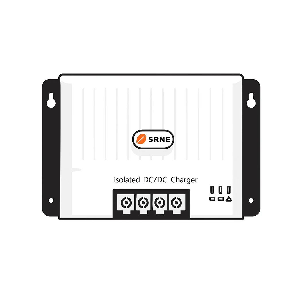
A battery to battery charger is a DC-DC unit that takes power from your vehicle's starter battery and alternator and delivers a controlled charge to your leisure battery. It solves the problem smart alternators create: voltage that drops too low to charge a second battery properly.

At Skyenergi, we supply these units alongside the cables, fuses and terminals that make an install straightforward. This guide walks through the full job in seven steps.
Tools and Safety Equipment
Gather everything before you touch the vehicle:
- Insulated spanners and a socket set
- Crimping tool for heavy cable lugs
- Multimeter for voltage checks
- Heat shrink and a heat gun
- Cable ties and a drill for mounting
- Safety glasses and insulated gloves
Work from the device toward the power source, never the reverse. Connecting live cables in the wrong order risks short circuits and burns (West Marine electrical installation guidance).
Step 1: Prepare the Vehicle and Isolate Both Batteries
Disconnect the negative terminal on the starter battery first, then the leisure battery. This kills the earth path before you handle any live positive cable.
Check both batteries with a multimeter before you start. A resting lead-acid or AGM battery should read around 12.6V. A lithium battery sits slightly higher.
Identify the positive and negative terminals on each battery. Positive posts are usually marked red, negative black. Get this wrong and you will damage the charger.
Now plan your cable route from the starter battery to the charger location. Keep runs as short as practical.
Step 2: Mount the Charger Unit
Pick a spot with airflow and away from direct heat. DC-DC chargers get warm under load, so a sealed battery box is a poor choice.
Mount the unit on a solid surface using the supplied brackets. Keep it within reach of both batteries to limit cable length. Every extra metre adds voltage drop.
Leave at least 50mm of clearance around the casing. This matters for units that rely on natural cooling rather than a fan.
Step 3: Choose the Best Cable Size for DC-DC Charger Runs
The best cable size for a DC-DC charger depends on three things: charger current, one-way run length, and the voltage drop you are willing to accept. Most guides quote a cable size without showing the maths, which is why so many installs underperform.
Voltage drop is the loss of voltage along a cable as current flows. Keep it under 3% of system voltage for a reliable charge, that is roughly 0.36V on a 12V system. Above that, the charger sees a depressed input voltage, derates its output and can refuse to start on a smart alternator.
Worked example: 30A charger, 6m one-way run
Use the round-trip distance (12m), not the one-way length. Copper resistivity is about 0.0175 ohm·mm²/m.
- 16mm² cable: resistance = (0.0175 × 12) ÷ 16 = 0.0131 ohm. At 30A, drop = 0.39V (3.3%). Marginal.
- 25mm² cable: resistance = (0.0175 × 12) ÷ 25 = 0.0084 ohm. At 30A, drop = 0.25V (2.1%). Comfortable.
So a 30A charger on a 6m run wants 25mm², not the 16mm² many tables suggest.
Quick sizing table
| Charger output | Run up to 3m | 3-6m | 6-10m |
|---|---|---|---|
| 20A | 10mm² | 16mm² | 25mm² |
| 30A | 16mm² | 25mm² | 35mm² |
| 50A | 25mm² | 35mm² | 50mm² |
These assume a 3% drop target and copper conductors. If you use CCA (copper-clad aluminium) cable, size up one step, its resistance is roughly 1.6× that of pure copper.
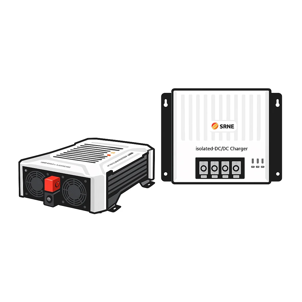
For a pre-matched setup, the 12V Battery To Battery Charger Kit with the SRNE DCI12-1230 ships with cable, connectors and fuses. If you need a longer run, size up from the kit cable using the table above.
Step 4: Meet the Fusing Requirements for Campervan Electrics
Fusing requirements for campervan electrics mean a fuse on every positive cable, close to the source. This protects the cable if it shorts against the chassis.
Fit a fuse rated just above the charger's maximum current. A 30A unit takes a 40A or 60A fuse depending on cable rating. A 50A unit needs a larger rating again.
Use a midi or ANL fuse holder with a proper mounting point. Never rely on the charger's internal protection alone.
| Charger Output | Suggested Fuse | Minimum Cable | Typical Run |
|---|---|---|---|
| 30A | 40-60A | 16mm² | Up to 5m |
| 50A | 60-80A | 25mm² | 5-8m |
| 50A (long run) | 80A | 35mm² | Over 8m |
Step 5: Wire the Ignition Switched Live for DC-DC Charger Control
The ignition switched live for a DC-DC charger tells the unit when the engine is running. Without it, the charger cannot tell a running alternator from a parked vehicle, and it will either drain the starter battery or refuse to charge.
There are three detection methods in common use, and knowing which one your charger uses determines how you wire it.
1. Voltage-threshold detection
The charger watches the input voltage and starts charging when it rises above a set point, typically 13.2V to 13.5V, and stops when it falls below about 12.8V. This works on older fixed-output alternators but is unreliable on smart alternators, which can sit at 12.4V at cruise and only spike to 14.5V under deceleration.
2. Dedicated ignition feed
A wire from a circuit that is live only with the ignition (or better, only with the engine running) tells the charger to activate. This is the most reliable method on Euro 5 and Euro 6 vehicles. Use a fuse tap on a circuit that drops out during cranking, or take a feed from the alternator warning lamp circuit if your vehicle still has one.
3. CAN-bus / engine-running signal
Many modern vans broadcast an engine-running or alternator-load message on the CAN bus. Some chargers, including several SRNE DC-DC models, can read this directly or accept a CAN-bus interface module. This is the cleanest option on stop-start vehicles, where the alternator may be inactive at traffic lights and a simple ignition feed would keep the charger running when it should not.
Smart alternator behaviour to expect
On a Euro 6 vehicle, expect the alternator to hold around 12.4-13.0V at steady cruise and rise to 14.4-14.8V only under braking or overrun. A charger that relies on voltage threshold alone will cycle on and off. A charger with a proper ignition feed or CAN input will charge continuously and correctly.
If your vehicle has stop-start, add a relay or use the charger's engine-running input so the unit shuts down when the engine stops at lights. Otherwise the charger will pull from the starter battery during the stop and flatten it.
For a setup that handles smart alternators and stop-start out of the box, the 12V Battery To Battery Charger Kit with the SRNE DCI12-1230 includes the ignition wiring and configuration guidance for Euro 5 and 6 vehicles. If you want higher output with the same smart-alternator compatibility, the Victron Orion XS 12/12-50A kit is the 50A option.

Step 6: Connect the Main Power and Earth Leads
Connect the earth lead first, then the positive cables, working toward the power source. This order reduces the risk of a live short.
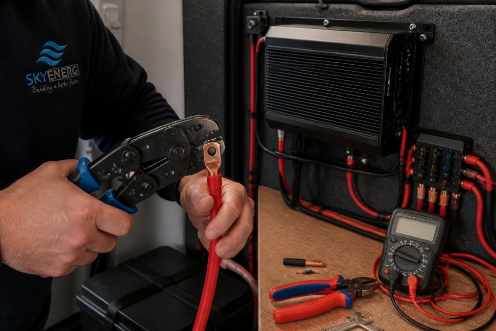
Crimp each terminal properly and seal it with heat shrink. A loose crimp creates resistance, heat and voltage drop.
Step 7: Test the Installation and Configure the Charger
Reconnect the leisure battery negative, then the starter battery negative. Check voltages at the charger input and output with a multimeter.
Frequently Asked Questions
Do I need a fuse between my starter battery and DC-DC charger?
Yes. Fit a fuse within 150-300mm of the starter battery positive terminal and another close to the auxiliary battery. Size the fuse about 20-30% above the charger's maximum input current. For a 30A charger, a 40A midi fuse works well; for a 50A unit, use a 60A fuse. The SRNE DCI12-1230 kit includes two 60A midi fuse holders and fuses. This protects the cable if it chafes or shorts, which is a real risk on long runs through a vehicle.
What is the correct order for connecting battery cables to a DC-DC charger?
Work from the device outward to the power source. First connect the charger's earth lead, then the ignition wire, then the auxiliary battery positive, then the starter battery positive, and finally the starter battery negative. When disconnecting, reverse the order. This sequence keeps live cables away from your tools and reduces the chance of shorting the positive terminal against the chassis. Always isolate both batteries before you begin.
Can I install a DC-DC charger with a lithium leisure battery?
Yes, but the charger must have a lithium charge profile. Standard lead-acid chargers will not fully charge a lithium battery and can damage it. The Victron Orion-Tr Smart and Orion XS both support lithium and lead-acid, selectable via the VictronConnect app. The SRNE DCI12-1230 also handles both chemistries. Set the absorption voltage to 14.2-14.6V for LiFePO4 and confirm the battery's BMS accepts the charge current.
How do I connect the ignition feed to a DC-DC charger?
Run a 1.5mm² cable from an ignition-switched live source, such as a fuse tap on a circuit that goes live with the engine, to the charger's remote on/off terminal. If your vehicle has a smart alternator, you may not need this wire because the charger can detect engine running from voltage fluctuations. The Victron Orion series supports both methods. Check the charger manual for the exact terminal layout before wiring.
Getting the wiring, fusing and charge profile right is what separates a system that lasts from one that fails on the road. Skyenergi supplies the batteries, chargers and accessories to build it properly, with the SRNE and Victron Orion kits covering most campervan and motorhome setups. Get started with Skyenergi and fit a charging system you can rely on.
Prev post

Alternatives to Fixed Solar Panels for Campervans
Updated on 18 September 2026
Next post

Fogstar Battery Alternative for Campervans: Skyenergi Picks
Updated on 17 September 2026


