




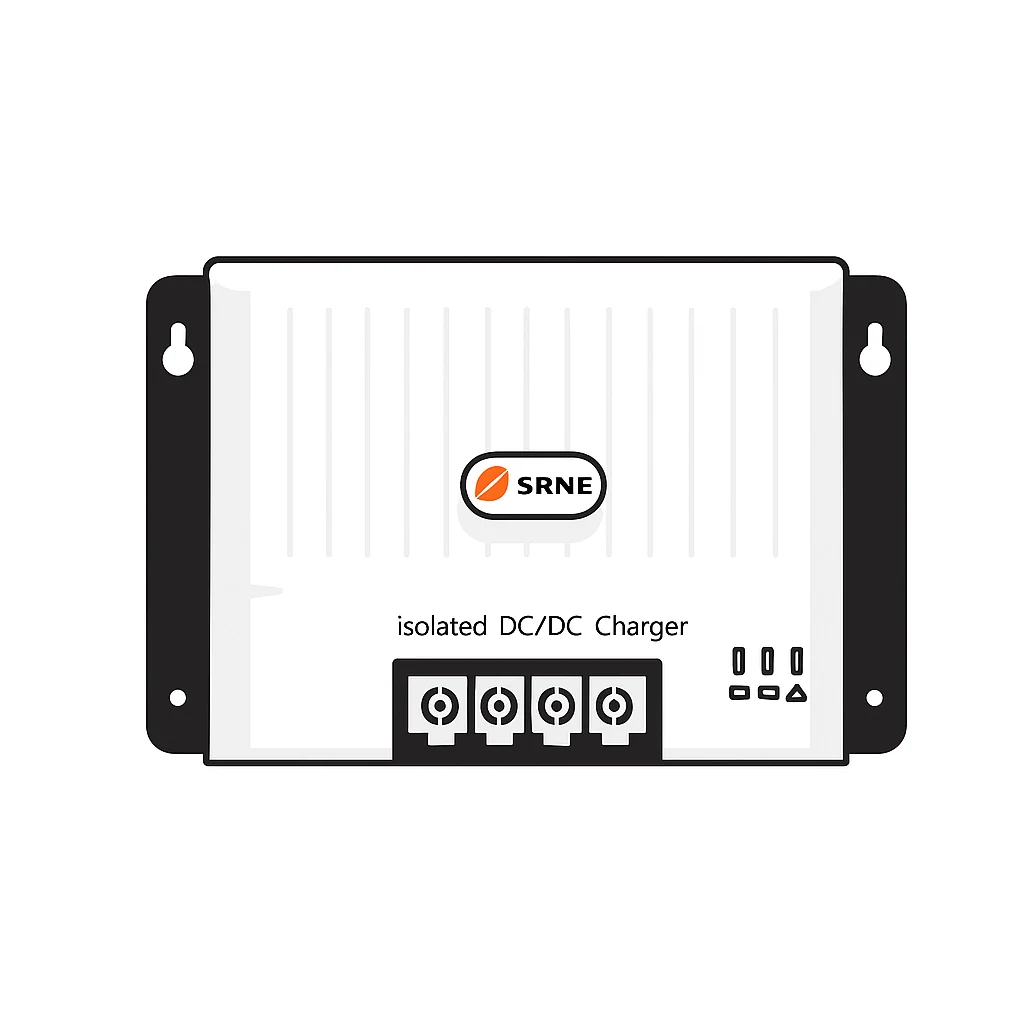

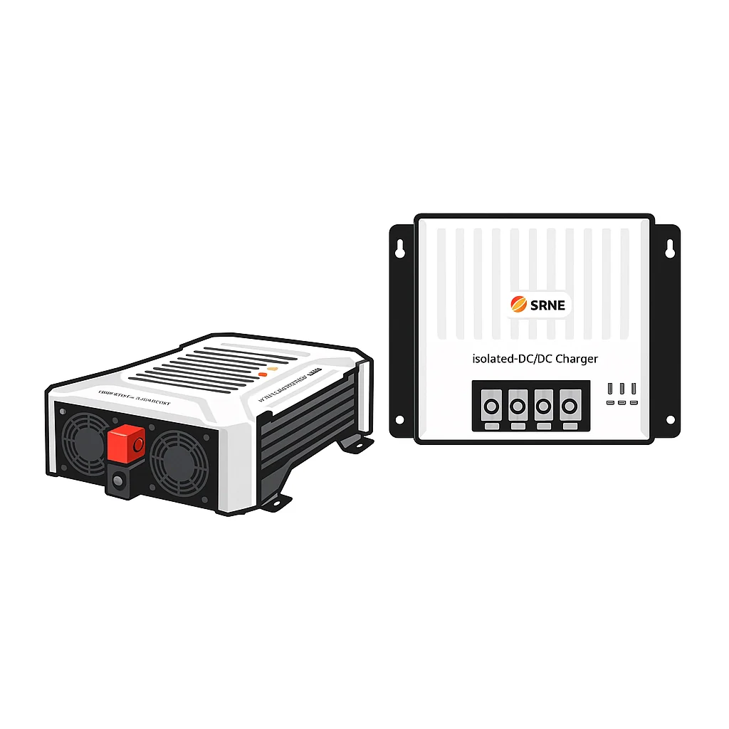


How to Wire a DC to DC Charger with Smart Alternator
Learn how to wire a DC to DC charger with smart alternator. Step-by-step guide covers ignition wire, fusing, cable sizing and lithium battery setup. Get.
Table of Contents
- What Is a Smart Alternator and Why It Needs a DC to DC Charger
- What You'll Need Before You Start Wiring
- Step-by-Step: How to Wire a DC to DC Charger with Smart Alternator
- DC to DC Charger Ignition Wire Connection: Voltage Sensing vs IGN Signal
- Fusing Requirements for Campervan Electrical Systems
- Best DC to DC Charger for Lithium Batteries
- Common Mistakes to Avoid
- Conclusion
- Frequently Asked Questions
Last Updated: September 20, 2026
What Is a Smart Alternator and Why It Needs a DC to DC Charger
A smart alternator is a variable voltage alternator that adjusts its output to save fuel and cut emissions. Instead of holding a steady 14V, it swings between roughly 12.5V and 15V in a 12V system, according to [Victron Energy's Orion XS(/products/12v-battery-to-battery-charger-kit-includes-victron-orion-xs-12-12-50a-dc-dc-battery-charger-with-built-in-bluetooth) technical documentation | victronenergy.com].
How to Identify If Your Vehicle Has a Smart Alternator
Check your alternator output with a multimeter while the engine runs. If voltage moves around, you have a smart alternator.
Look for these signs:
- Voltage reads below 13.5V at idle, then climbs when you lift off the throttle
- The vehicle has regenerative braking or stop-start
- It meets Euro 5 or Euro 6 emissions standards
- A "smart charging" or "battery management" message appears in the handbook
What You'll Need Before You Start Wiring
Gather your parts and tools first. A missing fuse holder mid-install is how mistakes happen.
Tools:
- Multimeter
- Crimping tool
- Cable cutters
- Heat shrink and a heat gun
- Socket set and drill
Parts:
- A DC to DC charger rated for your battery
- 8 AWG cable or larger for long runs
- An inline fuse for the input and output
- A fuse block
- Ring terminals and a chassis grounding point
- An ignition-switched 12V source for the IGN signal
Step-by-Step: How to Wire a DC to DC Charger with Smart Alternator
Here is the full install, from mounting to first charge. Work with the starter battery disconnected and take your time on the cable route.
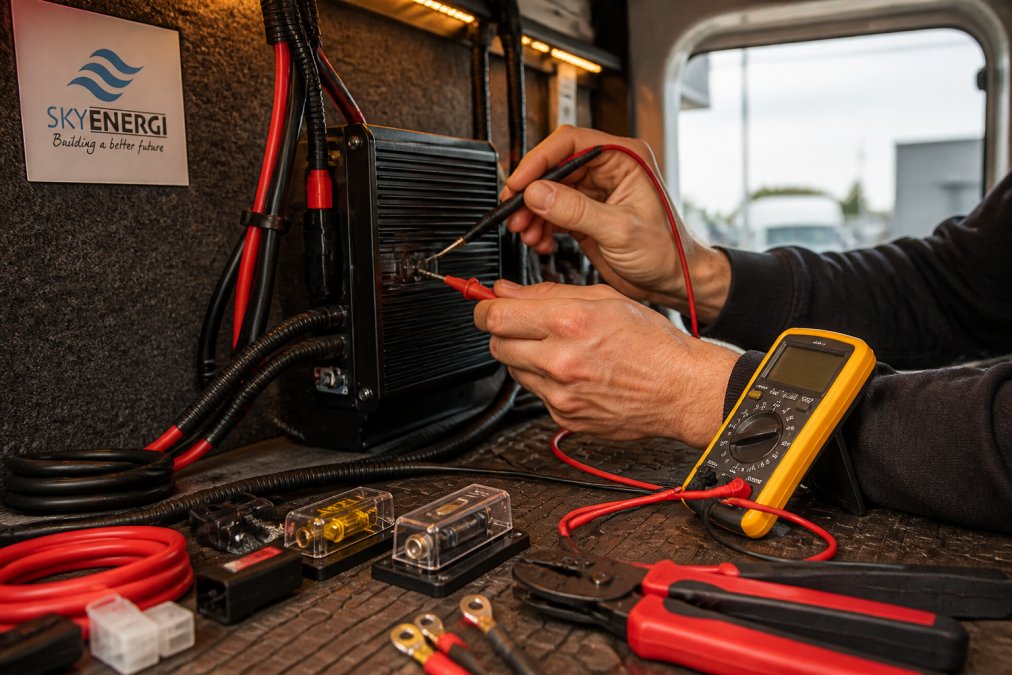
Step 1: Mount the Charger and Plan Your Cable Route
Mount the charger close to the auxiliary battery, in a dry, ventilated spot. Keep the input cable run as short as you reasonably can.
Plan the route before drilling anything:
- Avoid sharp edges and hot surfaces
- Keep cables away from CAN-bus wiring to reduce interference risk
- Allow slack at both ends for servicing
Step 2: Connect the Starter Battery to the Charger Input
Run the positive cable from the starter battery to the charger input. Fit an inline fuse close to the starter battery.
Then connect:
- Positive starter terminal to the charger input positive
- Charger input negative to a chassis ground
- The IGN signal wire to an ignition-switched source
Step 3: Wire the Auxiliary Battery to the Charger Output
Connect the charger output positive to the auxiliary battery positive, with its own inline fuse. Run the output negative to a solid chassis ground.
Step 4: Ground the Charger to the Chassis
Ground the charger body and both negative returns to the vehicle chassis. Scrape paint back to bare metal at the grounding point.
Step 5: Test and Configure the Charging Profile
Reconnect the starter battery. Start the engine and check the charger wakes up.
Then set your charging profile:
- Select lithium (LiFePO₄) or lead-acid to match your battery
- Confirm the absorption and float voltages
- Check the current limiting is set correctly
DC to DC Charger Ignition Wire Connection: Voltage Sensing vs IGN Signal
The trigger is the part of the install that decides whether the charger ever turns on. Get it wrong and you will have a perfectly wired charger that sits idle while your leisure battery slowly drains.
Why voltage sensing fails on a smart alternator
Voltage sensing works by watching the input voltage. When it rises above a threshold, the charger assumes the engine is running and starts charging. On a fixed-voltage alternator that threshold is easy to hit because the alternator holds a steady 14V or so.
12V Battery To Battery Charger Kit →
The three trigger methods
| Method | How it works | Best for |
|---|---|---|
| Voltage sensing | Triggers when input voltage rises above a set threshold | Older fixed-voltage alternators only |
| Ignition-switched 12V (IGN/ACC) | Triggers from a circuit that is live only with the ignition on | Smart alternators, Euro 5/6 vehicles |
| Engine-running detection (CAN or alternator signal) | Charger reads a data signal or the alternator's own output | Vehicles where no clean ignition source is available |
For most smart alternator vehicles the ignition-switched 12V source is the correct choice. It is simple, reliable and does not depend on the alternator's behaviour.
Where to pick up an ignition-switched source
This is where generic guides fall down. The right tap point depends on the vehicle, and picking the wrong one can trigger warning lights or upset the vehicle's electronics.
Common safe sources include:
- A spare ignition-switched fuse position in the cabin or engine bay fuse box, using a fused piggyback tap
- The vehicle's own auxiliary or leisure battery prep circuit, where fitted
- A dedicated ignition-switched feed from the fuse box that is not shared with safety-critical systems
Sources to avoid:
- Anything on the CAN-bus, including wiring to the instrument cluster, body control module or infotainment system
- Airbag, ABS, immobiliser or engine management circuits
- Circuits that stay live with the ignition off, such as the radio memory or interior lights
CAN-bus interference risk
Modern vehicles use the CAN-bus to carry data between modules. Tapping into a CAN-bus wire, or into a circuit that a module monitors, can cause error codes, warning lights, or in the worst case a vehicle that will not start. The risk is highest on vehicles with stop-start and regenerative braking, because those systems are already sensitive to battery current and voltage.
Wiring the trigger
Once you have a source:
- Fit an inline fuse close to the tap point, rated to the trigger wire.
- Run the trigger wire to the charger's IGN or trigger input, keeping it away from the main charge cables.
- Crimp and heat-shrink every joint.
- Confirm the charger wakes with the ignition on and sleeps with it off before you button everything up.
If your charger supports it, set the input voltage lockout a little below the alternator's lowest observed reading. That stops the charger dropping out when the smart alternator pulls voltage down during cruising, and it is the difference between a charger that works and one that cycles on and off all day.
Fusing Requirements for Campervan Electrical Systems
Fusing protects your cable and your vehicle. Every positive cable in the run needs protection at both ends.
Fit fuses like this:
- Inline fuse at the starter battery, rated to the cable
- Inline fuse at the auxiliary battery, rated to the cable
- A fuse block for any branch circuits
Best DC to DC Charger for Lithium Batteries
For lithium setups, you want a charger with a dedicated LiFePO₄ profile and smart alternator support. The Victron Orion range covers both.
Skyenergi's picks:
- Victron Orion XS 12/12-50A kit, £339.00: 50A output, up to 98.5% efficiency, IP65, fanless
- Victron Orion 30A kit, £210.00: adaptive 3-stage charging, Bluetooth
- Orion-Tr Smart 12/12 30A non-isolated, £152.80: remote on/off, engine running detection
- Orion-Tr Smart 12/12 18A isolated, £122.40: isolated output for cleaner installs
Common Mistakes to Avoid
Most install problems trace back to a handful of errors. Avoid these and your system will charge reliably.


- Skipping the IGN wire. Voltage sensing alone often fails on smart alternators, so the charger never wakes up.
- Undersized cable. Thin cable causes voltage drop and slow, hot charging.
- Poor chassis ground. A painted or loose ground gives erratic readings.
- Overloading the alternator. Add up your loads before fitting a high-output charger.
- No fuses. An unprotected positive cable is a fire risk.
Conclusion
Wiring a DC to DC charger with a smart alternator is a job you can do yourself, as long as you respect the IGN wire, the cable gauge and the fuses. Get those three right and the rest falls into place.
Frequently Asked Questions
Is a DC to DC charger bad for your alternator?
A correctly sized DC to DC charger will not damage your alternator. A 30A charger typically draws around 33A from the alternator, which is well within the capacity of most modern vehicle alternators. The charger also limits current draw, protecting the alternator from overload. However, if you install a charger with an output rating that exceeds your alternator's spare capacity, you risk overloading it. Always check your alternator's rated output before choosing a charger.
What is the purpose of the ignition (ACC) wire on a DC to DC charger?
The ignition or ACC wire tells the charger when the engine is running. Smart alternators vary their output voltage between 12.5V and 15V, so simple voltage sensing often fails to detect a running engine. A physical ignition-switched connection provides a reliable signal, ensuring the charger only activates when the engine is on. This prevents the charger from draining the starter battery when the vehicle is parked.
Can I connect a DC to DC charger directly to the starter battery?
Yes, the charger input connects to the starter battery positive terminal through an inline fuse. This is the standard wiring method. The charger draws current from the starter battery, which is continuously replenished by the alternator when the engine runs. Always fit a fuse close to the starter battery to protect the cable run, and use cable sized for the charger's current draw and the length of the run.
How does a DC to DC charger protect the vehicle's alternator?
A DC to DC charger limits the current it draws from the alternator to a set maximum. For example, a 30A charger draws approximately 33A, regardless of how depleted the auxiliary battery is. This controlled draw prevents the alternator from overheating or being overloaded, which can happen when a deeply discharged leisure battery is connected directly. The charger also isolates the auxiliary battery when the engine is off, preventing reverse drain.
Prev post

Solar Panel with Battery: Essential Guide for Off-Grid Power
Updated on 21 September 2026
Next post

What Is a BMS in a Lithium Battery: A Guide
Updated on 20 September 2026


